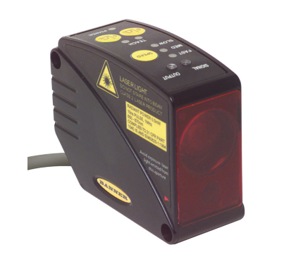
Sensor Banner LT3 (L-GAGE)
Sensor Banner LT3 (L-GAGE):
• Extremely long range: 5 m with white targets or 3 m with gray targets
• Banner’s unique scalable analog output automatically distributes the output signal over the width of the programmed sensing window
• Analog and discrete (switched) outputs in each sensor, with independent window limits
• Discrete output can be used for precise background suppression
• Choose NPN or PNP discrete output, plus 0 to 10 V dc or 4 to 20 mA sourcing analogoutput
• Fast, easy-to-use integrated push button TEACH-mode programming; no potentiometer adjustments
• Remote TEACH-function for security and convenience
• Output response is programmable for three speeds
• Choose 2 m or 9 m unterminated cable, or 8-pin Euro-style swivel quick-disconnect connector
• Rugged construction withstands demanding sensing environments; IEC IP67, NEMA
WARNING: Not To Be Used for Personnel
Protection
Never use this device as a sensing device for personnel protection. Doing so could lead to serious injury or death.
This device does not include the self-checking redundant circuitry necessary to allow its use in personnel safety applications. A sensor failure or malfunction can cause either an energized or de-energized sensor output condition.
CAUTION: Do Not Disassemble for Repair
This device contains no user-serviceable components. Do not attempt to disassemble for repair. Use of controls or adjustments or performance of procedures other than those specified herein may result in hazardous radiation exposure. A defective unit must be returned to the manufacturer.
Sensor Banner LT3 (L-GAGE) – Modelos
| Models | Sensing Distance | Cable | 2 | Discrete Output | Analog Output | |||||||||||||||||||||||||||||||
| LT3PU | 300 mm to 5 m (11.8 in to 16.4 ft) with a 90% reflectivity white card | 2 m (6.5 ft) 8-wire | PNP (Sourcing) | Analog Voltage (0 V dc to 10 V dc) |
||||||||||||||||||||||||||||||||
| LT3PUQ | 8-pin Euro-style QD | |||||||||||||||||||||||||||||||||||
| LT3NU | 2 m (6.5 ft) 8-wire | NPN (Sinking) | ||||||||||||||||||||||||||||||||||
| LT3NUQ | 8-pin Euro-style QD | |||||||||||||||||||||||||||||||||||
| LT3PI | 2 m (6.5 ft) 8-wire | PNP (Sourcing) | Analog Current (4 mA to 20 mA) | |||||||||||||||||||||||||||||||||
| LT3PIQ | 8-pin Euro-style QD | |||||||||||||||||||||||||||||||||||
| LT3NI | 2 m (6.5 ft) 8-wire | NPN (Sinking) | ||||||||||||||||||||||||||||||||||
| LT3NIQ | 8-pin Euro-style QD | |||||||||||||||||||||||||||||||||||
Sensor Banner LT3 (L-GAGE) – Theory of Operation
A short electrical pulse drives a semiconductor laser diode to emit a pulse of light. The emitted light is collimated through a lens, which
produces a very narrow laser beam. The laser beam bounces off the target, scattering some of its light through the sensor’s receiving
lens to a photodiode, which creates an electrical pulse. The time interval between the two electrical pulses (transmitting and receiving
the beam) is used to calculate the distance to the target, using the speed of light as a constant.
Multiple pulses are evaluated by the sensor’s microprocessor, which calculates the appropriate output value. The analog output
provides a variable signal (4 mA to 20 mA or 0 V dc to 10 V dc, depending on model) that is proportional to the target’s position within
the user-programmed analog window limits. The discrete (switched) output energizes whenever the target is located between the userprogrammed
discrete window limits. Window limits for the analog and discrete outputs may be the same, or they may be programmed
independently.

Low-power lasers are, by definition, incapable of causing eye injury within the duration of a blink (aversion response) of 0.25 seconds. They also must emit only visible wavelengths (400 to 700 nm). Therefore, an ocular hazard may exist only if individuals overcome their natural
aversion to bright light and stare directly into the laser beam.
These lasers are required to have a “hazard” label and to have an indicator light to indicate that laser emission is occurring.
When operating a Class 2 laser:
• Do not stare at the laser.
• Do not point the laser at a person’s eye.
• Mount open laser beam paths either above or below eye level, where practical.
• Terminate the beam emitted by the laser product at the end of its useful path.
Sensor Banner LT3 (L-GAGE) – Instruções de Configuração
Sensor Power-Up and Laser-Enable
Power up the sensor for 30 minutes to allow the sensor’s internal temperature to stabilize before operating or attempting to program
the sensor. If the sensor is used in applications where the temperature is several degrees higher or lower than the ambient temperature, allow the sensor to stabilize in that condition before programming the window limits. The range decreases when the sensor warms up.
The Laser-Enable feature allows the sensor to be continually powered and enabled only when being used. This eliminates the need for
the extended warm-up period between uses.
The sensor’s red Signal LED indicates the condition of the received signal from the object being measured. When programming the
window limits, this LED must be on (not flashing) for the sensor to accept the setting. To ensure the received signal will not be marginal
during operation, move the target object 300 mm beyond the furthest desired switch point during setup and verify the signal LED is still
on.
Indicadores

Power ON/OFF LED (green)—Indicates the operating status of the sensor.
| Power ON/OFF LED Status | Indicates | |||||||||||||||||||||||||||||||||||
| Off | Power is off | |||||||||||||||||||||||||||||||||||
| Flashing at 2 Hz | Discrete output is overloaded (Run mode) | |||||||||||||||||||||||||||||||||||
| Flashing at 1 Hz | Power is on; laser is disabled | |||||||||||||||||||||||||||||||||||
| On | Power is on; the sensor is operating normally and the laser is enabled
|
|||||||||||||||||||||||||||||||||||
Power-Up/Laser-Enable Indicators—When powering up the sensor all LEDs turn on for one second. Allow a 0.6-second delay for LaserEnable.
| Selected Response Speed | Laser-Enable Time | Laser-Disable Time | ||||||||||||||||||||||||||||||||||
| Slow | 150 ms | 50 ms | ||||||||||||||||||||||||||||||||||
| Medium | 60 ms | |||||||||||||||||||||||||||||||||||
| Fast | 51 ms
|
|||||||||||||||||||||||||||||||||||
Output LED (amber)—Lights when a target is sensed within the programmed discrete window.
Response Speed (amber)—Indicates the response speed setting.
Signal LED (red)—Indicates the strength and condition of the sensor’s incoming signal.
| Signal LED Status | Indicates | |||||||||||||||||||||||||||||||||||
| On | Good signal | |||||||||||||||||||||||||||||||||||
| Off | No signal is received or the target is beyond the range limitations of the sensor (with some tolerance beyond the recommended minimum and maximum sensing distance) | |||||||||||||||||||||||||||||||||||
| Flashing | Marginal signal strength (cannot teach limits)
|
|||||||||||||||||||||||||||||||||||
Response Speed
Before setting window limits, use the sensor’s speed button to toggle between the three response speed settings. The selected speed
will be indicated by one of the three response speed indicator LEDs.
| Discrete Output Response Speed | Analog Output Frequency Response (-3dB) | |||||||||||||||||||||||||||||||||||
| Slow | 100 ms ON and OFF | 4.5 Hz (100 ms average/4 ms update rate) | ||||||||||||||||||||||||||||||||||
| Medium | 10 ms ON and OFF | 45 Hz (10 ms average/2 ms update rate) | ||||||||||||||||||||||||||||||||||
| Fast | 1 ms ON and OFF | 450 Hz (1 ms average/1 ms update rate)
|
||||||||||||||||||||||||||||||||||
Sensor Banner LT3 (L-GAGE) – Programming
Remote Programming—To program the sensor remotely or to disable the keypad, use the Remote Programming function. Disabling the
keypad prevents accidental or unauthorized adjustment of the programming settings. Connect the yellow wire of the sensor to +5 V dc
to 24 V dc, with a remote programming switch connected between them.
Programming is accomplished by following the sequence of input pulses. The duration of each pulse (corresponding to a push button
“click”) and the period between multiple pulses are defined as “T”: 0.04 seconds ≤ T ≤ 0.8 seconds.
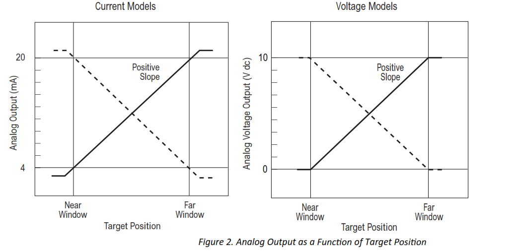
Analog Output Slope—The L-GAGE LT3 Sensor may be programmed for either a positive or a negative output slope, based on which
condition is taught first. If the near limit is taught first, the slope will be positive. If the far limit is taught first, the slope will be negative.
Banner’s unique scalable analog output (patent pending) automatically distributes the output signal across the width of the
programmed sensing window.
In the event of analog signal loss for longer than 2 seconds, the analog output goes to 0 V dc or 3.6 mA, which may be used to trigger an
alarm.
Teaching Limits for Background Suppression
For some applications, ignoring objects beyond a certain distance may be required. To suppress the background, place a target object at
the selected distance, and teach the position twice. The sensor’s discrete output will activate when an object is detected between the
sensor’s minimum sensing distance and the taught position.
Program either analog output or discrete output first. For the button or the remote wire, a button click or pulse is: 0.04 seconds ≤ T ≤
0.8 seconds.
Sensor Banner LT3 (L-GAGE) – Teaching Independent Limits for Either Output
Teaching Analog Limits Using the Auto-Zero Feature (Analog Output)—For some analog applications, a sensing distance switch point
centered within a sensing window may be required. The TEACH procedure is simple: teaching the same limit twice causes the sensor to
program a window centered on the position taught. This window is 1 m wide (taught position ± 0.5 m).
To exit Program mode without saving changes, press and hold the same push button (or hold the remote line high) for longer than 2
seconds (before teaching the second limit). The sensor will revert to the last saved program.
1. Sensor Banner LT3 (L-GAGE) – Enter programming mode.
| Method | Action | Result | |||||||||||||||||||||||||||||||||
| Push Button | Push and hold the button for either output for longer than 2 seconds. The sensor will return to RUN mode if first TEACH-condition is not registered within 120 seconds. | The appropriate TEACH-LED turns ON. The sensor is waiting for first limit. | |||||||||||||||||||||||||||||||||
| Remote Input | No action required. | ||||||||||||||||||||||||||||||||||
2. Sensor Banner LT3 (L-GAGE) – Teach the first limit.
| Method | Action | Result | |||||||||||||||||||||||||||||||||
| Push Button | Position the target for the first limit. Click the same button. | The appropriate TEACH LED turns ON then flashes at 2 Hz. The sensor learns the first limit and waits for the second limit. | |||||||||||||||||||||||||||||||||
| Remote Input | Position the target for the first limit. T For the discrete output, single-pulse the remote line. T T For the analog output, double-pulse the remote line. T
|
||||||||||||||||||||||||||||||||||
3. Teach the second limit.
| Method | Action | Result | |||||||||||||||||||||||||||||||||
| Push Button | Position the target for the second limit. Click the same button. | The TEACH LED goes OFF. The sensor learns the second limit and returns automatically to Run mode. | |||||||||||||||||||||||||||||||||
| Remote Input | T Position the target for the second limit and single-pulse the remote line.
|
||||||||||||||||||||||||||||||||||
4. Sensor Banner LT3 (L-GAGE) – Program the second output by repeating steps two and three.
Teaching Identical Limits to Both Outputs
When teaching limits simultaneously, both the outputs will have identical limits.
To exit Program mode without saving changes, press and hold the same push button (or hold the remote line high) for longer than 2
seconds (before teaching the second limit). The sensor will revert to the last saved program.
1. Enter programming mode.
| Method | Action | Result | |||||||||||||||||||||||||||||||||
| Push Button | Push and hold the button for either output for longer than 2 seconds. The sensor will return to RUN mode if the first TEACH condition is not registered within 120 seconds. | The appropriate TEACH LED turns ON. | |||||||||||||||||||||||||||||||||
| Briefly click the other output button. | The appropriate TEACH LED turns ON. The sensor is waiting for the first limit. | ||||||||||||||||||||||||||||||||||
| Remote Input | No action required. | ||||||||||||||||||||||||||||||||||
2. Teach the first limit.
| Method | Action | Result | |||||||||||||||||||||||||||||||||
| Push Button | Position the target for the first limit. Click either output button. | Both TEACH LEDs flash at 2 Hz, alternating red and green. The sensor learns the first limit and waits for the second limit. | |||||||||||||||||||||||||||||||||
| Remote Input | T T T Position the target for the first limit, then triple-pulse the remote line. T T |
Both TEACH LEDs turn ON. The sensor learns the first limit and waits for the second limit. Both TEACH LEDs flash at 2 Hz, alternating red and green.
|
|||||||||||||||||||||||||||||||||
3. Teach the second limit.
| Method | Action | Result | |||||||||||||||||||||||||||||||||
| Push Button | Position the target for the second limit. Click either output button. | Both TEACH LEDs go OFF. The sensor learns the second limit and returns automatically to Run mode. | |||||||||||||||||||||||||||||||||
| Remote Input | T Position the target for the second limit, then single-pulse the remote line.
|
||||||||||||||||||||||||||||||||||
Sensor Banner LT3 (L-GAGE) – Enabling or Disabling the Push Button
In addition to its programming function, the remote line may be used to disable the push buttons for security. Disabling the push
buttons prevents undesired tampering with the sensor configuration settings.
1. Connect the sensor’s gray wire.
2. Four-pulse the remote line to enable or disable the push button.
The sensor toggles between enable and disable settings and returns to RUN mode.
Instruções de Instalação

Especificações
Sensor Banner LT3 (L-GAGE) – Sensing Range (Diffuse Model)
90% White card: 0.3 to 5 m
18% Gray card: 0.3 to 3 m
6% Black card: 0.3 to 2 m
Supply Voltage and Current
12 V dc to 24 V dc (10% maximum ripple)
108 mA maximum at 24 V dc or [2600/V dc] mA
Sensor Banner LT3 (L-GAGE) – Supply Protection Circuitry
Protected against reverse polarity and transient voltages
Delay at Power-up
1 second; outputs do not conduct during this
time
Sensor Banner LT3 (L-GAGE) – Sensing Beam
658 nm visible red IEC and CDRH Class 2 laser
Radiant output power: 0.5 mW maximum
Typical beam dia: 6 mm
Typical laser
lifetime: 75,000 hours
Sensor Banner LT3 (L-GAGE) – Output Protection
Protected against short circuit conditions
Factory Default Settings
100 ms response speed
Analog/discrete window limits 0.3 m to 5 m using a 90%
reflectivity white card
Positive analog slope
Push buttons enabled
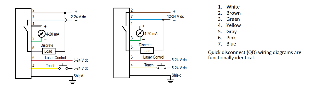
Sensor Banner LT3 (L-GAGE) – Laser Control
Enable: connect red wire to +5 to 24 V dc
Disable: connect to 0 to +1.8 V dc (or open connection)
Sensor Banner LT3 (L-GAGE) – Construction
ABS housing; acrylic window; ABS/polycarbonate blend quick disconnect fitting
Sensor Banner LT3 (L-GAGE) – Connections
2 m (6.5 ft) or 9 m (30 ft) shielded 7-conductor (with drain) PVC-jacketed
attached cable or 8-pin M12/Euro-style quick-disconnect
Output Rating (Discrete)
100 mA maximum
Off-state leakage current: < 5 μA
Output saturation NPN: < 200 mV at 10 mA and < 600 mV at 100 mA Output
saturation PNP: < 1.2 V at 10 mA; < 1.6 V at 100 mA
Output Rating (Analog)
Voltage output: 2.5 kΩ minimum load impedance
Current output: 1 kΩ maximum at 24 V; maximum load resistance =
[Vcc-4.5/0.02 Ω]
Output Response Time (Discrete)
Fast: 1 ms ON and OFF
Medium: 10 ms ON and OFF
Slow: 100 ms ON and OFF
Output Response Time (Analog voltage output (-3 dB))
Fast: 450 Hz (1 ms average/ 1 ms update rate)
Medium: 45 Hz (10 ms average/ 2 ms update rate)
Slow: 4.5 Hz (100 ms average/ 4 ms update rate)
Output Configuration
Discrete (switched): SPST solid-state switch; choose NPN (current sinking) or
PNP (current sourcing) models
Analog output: 0 V dc to 10 V dc or 4 mA to 20 mA
Discrete Output Hysteresis
(Diffuse model)
Fast: 10 mm
Medium: 5mm
Slow: 3mm
Minimum Window Size
Diffuse model: 20 mm
Remote Teach Input
18 kΩ minimum (65 kΩ at 5 V dc)
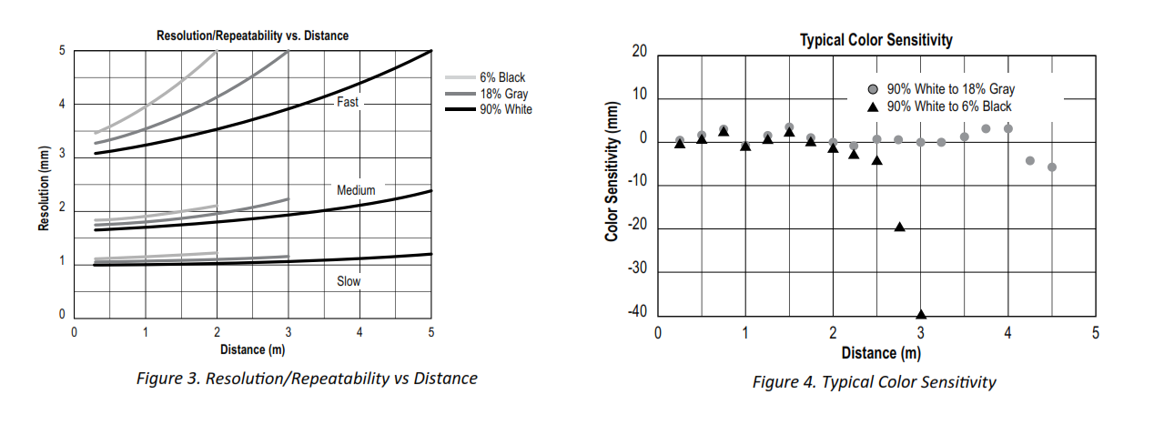
Resolution/Repeatability
See Performance Curves
Linearity
± 30 mm from 0.3 to 1.5 m; ± 20 mm from 1.5 to 5 m
(Specified at 24 V dc, 22° C using a 90% reflectance white card)
Temperature Effect
Diffuse models: < 2mm / °C
Environmental Rating
IEC IP67; NEMA 6
Operating Conditions
0 °C to +50 °C (+32 °F to +122 °F)
90% at +50 °C maximum
relative humidity (non-condensing)
Certifications Sensor Banner LT3 (L-GAGE)

Application Note
Allow 30-minute warm-up before programming or operating
Curvas de Performance
Para mais informações sobre o Sensor Banner LT3 (L-GAGE), clique aqui.